• There has been a recent cluster of spammers accessing BARFer accounts and posting spam. To safeguard your account, please consider changing your password. It would be even better to take the additional step of enabling 2 Factor Authentication (2FA) on your BARF account. Read more here.

Reanimating a greybike RVF400 (NC35)

Rummaging in my garage yielded a trunkful of items for donation to Goodwill, two boxes of toys for my friend's kids, and ....drum roll.....the missing Starrett micrometers! I even found yet another set of, you guessed it, feeler gauges. :rofl:rofl:rofl I suppose better late than never.
 
Still having fun

Can you believe it? My RVF saga began one year ago! My enthusiasm for the project is as strong as day one. Notable events: finding the bike, laying eyes on the RVF for the first time :love, setting up a shop, solving missing keys puzzle, rancid gas shit show, watching the dash light up, valve reshimming, and carburetor rebuild. Notably, making friends with BARFer Anthony Cool dude :smoking and talented wrencher :eboy. We text all the time bouncing ideas off of each other and share wins and fails. Cheers, mate!

Truthfully, I'm a wee bit sad that everything has taken longer than anticipated - I once believed it would take six months at most to be whizzing through the Santa Cruz mountains. Wishful thinking. One year ago seller, Mark, asked me to send him a movie of the bike running because he hadn't heard for it for 7 years. With naïve optimism I vowed "No problem! Give me a month or two".:orly

Progress has often been two steps forward and one step back (sometimes two or three!). For sure a lot of :cry :teeth :dunno :facepalm :mad and :party. Best, I’m still having a tons o’ fun! :ride

Obviously BARF has played a large part in helping me move forward. Many of you have “been there, done that” and have kindly given advice, wisdom and words of encouragement. A lot like going on a ride with more experienced riders I’ve tried to follow their “lines” and even try things on my own. :thumbup to TheNewWazzoo for his sweet RVF project thread and giving me the needed encouragement to start my own project thread.

Without a doubt, the biggest challenge has been the carburetors – diassembling them was intimidating and time consuming. It was trial by fire. :hail to Bill for his sage advise and detailed explanations. You da man!. No doubt there was added pressure knowing most of the RVF's parts are hard to come by or NLA added to the stress of working on a grey market bike. If available, parts can be pricey and have to be sourced from Japan, Thailand or the UK. Being a rookie at this I didn’t want to make any irreparable mistakes. I worked cautiously one measured step at a time.

When I find the time, I will post details and more current developments. Stay tuned.
 
Last edited:
Great work Rick, it's wonderful to see that bike getting the attention to detail it deserves! Looking forward to seeing and hearing that video.

-Bill
 
SESSION 38: Carb reassembly

Dear peanut gallery, I have 57 days left :twofinger

Float heights set. Next assemble the bowls: a fresh coat of silicone vacuum grease on the new Viton O-rings so they stay stuck to the bowls while I maneuver them into place. Tighten the three new stainless steel M5 socket head screws (spring lock-washers installed) with a 4mm hex driver until snug. Repeat three more times. Done.

Not knowing where to start, I used the LiteTek rebuild kit as a guide. The parts came grouped in bags (see Session 33). One bag at a time, I cut them open and installed the parts. O-rings for needle, pilot screw, drain screw, overflow, fuel-tee and vacuum breather. I gave each item a thin coating of vacuum grease and then installed them. Once the new seals were in place I moved on to assembling the newly minted items to each of the 4 carburetors.

Needle Slides: Needles into flat slides > flat slides into carb bodies > diaphragms greased > diaphragm seated > spring in > cover on > three screws. Done.

Pilot Screw: screw into carb bodies > bottom out > back out 1-5/8” turns (I blew off the previous tuner's setting and went with stock). Done.

Main Jets: Screw in emulsion tubes (mindful of differences between fronts and rears) > screw in main jets (using non-tapered slotted driver). Done.

Drain Screws: Screw into float bowls. Done.

Plastic Tee Tubes: Easy, slip on O-rings. Done

With the easy stuff out of the way, it was time to reassemble the entire carburetor assembly. Two parts are responsible for this: a threaded metal rod in front for carbs 2 & 4, similar in back for 1 &3, and the diecast airbox bottom. Using photos and movies that I made during the teardown I loosely position the carbs in their respective positions and work the fuel tees between the carbs. I couple the sync linkages and then I skewered thru the carbs and the spacers with the rods. This puts the parts in alignment and gives form. Next I pressed everything together like a sandwich and secured the rod ends with nuts and button up with 10mm wrenches. They become a hell of a ridged structure.

Next attach the airbox lower plate. Slap on the substantial and greased airbox seals. I loosely placed the plate atop the carb assembly and finagle the air funnels in place - the tall ones in front. They key to the carbs and I press the plate into place and put the thin sheet metal safety brackets threaded with M6 screws into place. I opted for new stainless socket screws btw. I snug the screws in place sans torque wrench and bend the thin metal tabs over. Their purpose to prevent any loose screw from dropping into a cylinder and wreaking havoc. Carbs done and ain't they a beaut? :drool

:rolleyes Confession: the carb rebuild happened over several weeks. So it didn't progress nearly as linear and cleanly as I wrote :bs. I went through two fails requiring a complete tear down. Each time I did something lame but learned. Third time is a charm. It took a a lot of time and effort but I am mostly satisfied with the results. Hey, and I had no missing or leftover parts :thumbup
 

Attachments

  • NC35 carb assy airbox side 2.jpg
    NC35 carb assy airbox side 2.jpg
    52.7 KB · Views: 56
  • NC35 carb assy airbox side 4.jpg
    NC35 carb assy airbox side 4.jpg
    52.9 KB · Views: 42
  • NC35 carb assy airbox side 6.jpg
    NC35 carb assy airbox side 6.jpg
    49.4 KB · Views: 57
  • NC35 carb assy airbox side 8.jpg
    NC35 carb assy airbox side 8.jpg
    44.6 KB · Views: 45
  • NC35 carb assy engine side 2.jpg
    NC35 carb assy engine side 2.jpg
    57.6 KB · Views: 50
  • NC35 carb assy engine side 4.jpg
    NC35 carb assy engine side 4.jpg
    62.5 KB · Views: 42
  • NC35 carb assy engine side 6.jpg
    NC35 carb assy engine side 6.jpg
    63 KB · Views: 53
  • NC35 carb assy engine side 8.jpg
    NC35 carb assy engine side 8.jpg
    56 KB · Views: 45
So much patience Rick!
Much satisfaction though:teeth

Don't let Pierre anywhere near your bike.
 
fuck that guy and his sharpie signature

What do you call a dehydrated Frenchman? :rolleyes

Groaner I know. My classmate Pierre used to always tell it.
 
So much patience Rick!
Much satisfaction though:teeth

Don't let Pierre anywhere near your bike.

I won't but I will drill mount a cigarette lighter outlet in the fairing, ya know, for an electric tire pump. :laughing
 
Session 39: Bench Synching

The day was Saturday, one day before the anniversary. With carbs all assembled it was time to bench synch. Why sync? How about smooth power delivery, steady idle, no backfiring at deceleration, optimal power, etc. It's the process of adjusting the 4 carburetors work in concert with each other. It's a "gross" setting, a ball park, aka macro adjustment. Proper adjustment needs to happen on the bike as each cylinder differs and proper on the bike balancing should to accommodate this.

Bench synching is done off the bike and on the work bench (I still like the dining room table). Several suggestions from lots of folks with their preferred techniques all arguably legit: drill bits as gauge pins, some argued bias to just cracked vs. 1/8" open, etc. In theory I think as small as practicable say 0.010" [0.25mm] gauge pin in all throats. But I don't have gauge pins and damned if I'm going to go buy more gauges. So instead I just eyeballed them.

To do this I took off my eyeglasses because I see detail a lot better that way. Hold the carb 5" from my face and roll the throttle back and forth observing the butterflies and how they open. Do they open simultaneously/synchronously or do the gaps develop at a different rate. Well they looked like they all got along really well each mimicking the next. Each showing the same movements and gaps to my old sharp eyes. :laughing

Oh yeah, when I disassembled the carbs I didn't tamper with the synch screws - I let them alone figuring maybe the previous tuner set them right. Fingers crossed. Also, the proper way is to adjust on the bike with the engine is running. I still haven't decided DIY yardstick sync gauges or a manufactured set. We will see.

Okay, with carbs ready to install I was eager to get them attached to the engine. If I could pull this off 365 days to the day it would be epic. Tomorrow would be the day.
 
Why sync? How about smooth power delivery, steady idle, no backfiring at deceleration, optimal power, etc.
My XR650L backfires like crazy on deceleration. Maybe I need to sync it's one carburetor. Anybody know how to do that? :laughing
 
My XR650L backfires like crazy on deceleration. Maybe I need to sync it's one carburetor. Anybody know how to do that? :laughing

Lactose-free milk?
 
SESSION 40: Part 1 - Valve Covers & Carburetor Insulator Installation

The day began perfectly: stunning spring weather, breakfast at Philz with Jessica, deep dive in home garage for micrometers, discover micrometers (and more), and Goodwill drop-off. With domestic duties accomplished I hightail it over to the bat cave with the goal of making the RVF breathe its first breath on it's first anniversary (Sunday 4/15). It would be a perfect birthday present ;)

Step 1: Reshimming effort completed it was time to reinstall the front and rear valve covers. The covers go on easily each cover marked with “IN” informing the proper orientation of the cover. The one with a vent port goes in back for cylinders #1 & #3.

Months ago I had cleaned up and secured the old gaskets with RTV. I can’t remember if the Haynes manual said to use RTV as I may have read it elsewhere :dunno. IMO can't hurt.

The covers are secured by four flanged nuts and a thick metal washer with a rubber over-mold. I borrowed Anthony's Park Tools ratcheting torque wrench. Very nice tool :thumbup. 10Nm (7in-lbf) buttons everything up. Easy.

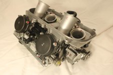
Step 2: Check the carb assembly one last time. I rechecked each screw and nut for the umpteenth time to make sure everything was tight and tidy. All good.

Step 3: Hello infamous carb insulators. Four short and flexible tubes whose sole purpose is to structurally couple and provide passage for the carburetor mixture directly into the engine cylinders. Molded in rubber they are compliant and ensure a leak free system like a coolant hose but without any internal fiber reinforcement (the pressures are much lower as are the temps).

I look back and chuckle knowing how clueless I was when it came to removing the carbs. What a newb! :laughing I hadn't no idea what an insulator was, how anything fit together, or that insulators can harden to a rigid plastic. Because I'm a weakling I resorted to almighty leverage and used a pry bar to pop the carbs off the bike. I'd have no hesitation to use the same technique next time.

Also recall my rubber softening experiment testing methyl salicylate (wintergreen oil) as a rubber restorer. It works! Rubber becomes soft but cracks don't mend. I'll have to dig up those test parts and see what they look like after 10 months of sitting...somewhere. :rolleyes

Anyyyways, to be safe I purchased new OEM insulators from Stuart at Rising Sun Cycles. They were something like $12 each. The new ones have a hardness similar to tire rubber.

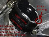
There are two part numbers for the insulators – the bike taking two of each. Part 1 has markings for cylinders #2 & #3 the Part 2 for cylinders #1 & #4. The insulators require two clamps each: engine side (lower) and carb side (upper).

The clamps are like a typical hose clamp plus they have a single hole in side to fit over a small boss on the rubber’s side. Its function is to index the band and prevent spinning out of position. Forcing a screw driver into the screw torques the band to spin and we don't want that. It also works out that the clamps get positioned with clearance (just barely) for a right angle driver to engage the idle mixture screw as necessary.

INSULATOR and LOWER CLAMP INSTALL:
1 Install lower clamp on insulator
2 Lube engine port and insulator interior and with silicone vacuum grease
3 Slip insulator onto correct cylinder port while ensuring the rib on the engine casting aligns with the notch in the rubber. This places the insulator in the orientation the Honda engineers intended.
4 Tighten the clamps to the max with a Phillips driver (8mm nut driver too fat to engage adequately) until the clamp flanges bottom out on the trapped spacer.
5 The rubber gets squeezed on like crazy. I seriously doubt any leaks there.
Engine side done.

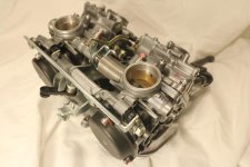
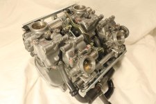
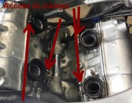
The lower clamps were easy to secure because the carbs were absent. The upper clamps, on the other hand, must be tightened after the carbs are mated making access possible only from the sides. Since the clamps can go on either LEFT or RIGHT facing, I played with different configurations until I settled on one that was optimal for access with a 16” Phillips driver. In the end I set it such that clamps #2, #4, & #3 will be tightened from the left side of the bike while cylinder #1 will be from the right.

The bed has been made for docking the carburetors :thumbup. This is going to be fun or a PITA.
 

Attachments

  • 0 S40 Insulators and fuel cocks.jpg
    0 S40 Insulators and fuel cocks.jpg
    229.1 KB · Views: 40
  • 1 S40 Valve cover bolt and rubber mount.jpg
    1 S40 Valve cover bolt and rubber mount.jpg
    81.9 KB · Views: 36
  • 2 S40 Valve cover install.jpg
    2 S40 Valve cover install.jpg
    73.8 KB · Views: 42
  • 3 S40 Valve cover Park torque wrench.jpg
    3 S40 Valve cover Park torque wrench.jpg
    117.4 KB · Views: 37
  • 4 S40 Carb insulator and clamp.jpg
    4 S40 Carb insulator and clamp.jpg
    76.2 KB · Views: 36
  • 5 S40 carb insulator features.jpg
    5 S40 carb insulator features.jpg
    96.6 KB · Views: 35
  • 6 S40 Carb insulator 3 test access.jpg
    6 S40 Carb insulator 3 test access.jpg
    90.1 KB · Views: 39
  • 7 S40 Insulator clamp fully tightened.jpg
    7 S40 Insulator clamp fully tightened.jpg
    88.4 KB · Views: 32
  • 8 S40 carb insulator clamps final.jpg
    8 S40 carb insulator clamps final.jpg
    81 KB · Views: 39
Oof, all this attention to detail, ultrasonic carb cleaning, full disassembly... then put back together with a cheap Taiwanese torque wrench? >.<
 
Oof, all this attention to detail, ultrasonic carb cleaning, full disassembly... then put back together with a cheap Taiwanese torque wrench? >.<
If it's reasonably accurate, why does it matter how much it cost or what country it came from? It tightens bolts the same way as an expensive wrench.
 
If it's reasonably accurate, why does it matter how much it cost or what country it came from? It tightens bolts the same way as an expensive wrench.

Sure, but I would guess that if someone's cheaping out on a tool, they're likely not going to spend money to get it calibrated. Additionally, my personal experience, more often than not, is that you get what you pay for with precision pieces.
 
Back
Top