• There has been a recent cluster of spammers accessing BARFer accounts and posting spam. To safeguard your account, please consider changing your password. It would be even better to take the additional step of enabling 2 Factor Authentication (2FA) on your BARF account. Read more here.

Reanimating a greybike RVF400 (NC35)

Driver bits have different shapes

Here are some photos showing the variety of shapes for flat blade driver bits. Maybe there isn't a standard.

The driver bit that fills the slot is less likely to cam out or damage the screw.
Sloped faces apply force on small area :thumbdown.
Flat faces contact more area minimizing damage :thumbup
 

Attachments

  • 0 Main jet slot.jpg
    0 Main jet slot.jpg
    43.8 KB · Views: 17
  • 1 Daiso bit.jpg
    1 Daiso bit.jpg
    50.9 KB · Views: 19
  • 2 HF 4-in-1.jpg
    2 HF 4-in-1.jpg
    48.7 KB · Views: 20
  • 3 Kirkland bit.jpg
    3 Kirkland bit.jpg
    52.4 KB · Views: 22
Session 26: Pilots and Jets

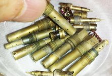
Tonight I got the main jets out of the emulsion tubes without incident :) The previously stubborn parts had soaked for about 24 hours in acetone to dissolve the varnish that was gluing the parts together. I removed them from their bath, slid emulsion tubes tube-end-first into the 7mm socket then used my best-fit driver to unscrew the main jets. Success! the parts separated easily. :thumbup

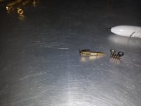
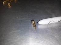
With that out of the way I moved on to the pilot mixture screw. It is another brass part but this time with a cross slotted pattern a cruder version of a familiar Phillips shape. This was simple two perpendicular slots running across the head of the screw. In any case, though the Phillips driver was a crude fit it didn't matter as the screw were a very loose fit and the parts weren't bound with varnish - they turned easily. Online and the Haynes manual instructed to carefully count the number of turns the screws were from full insertion. To do this you simply count how many clockwise turns it takes until the screw stops and then jot down your findings. The manual says the NC35 should have a nominal setting of 1.625 (1-5/8) turns.

So my results were different from factory:
#1 = 1.5 turns
#2 = 1.75 turns
#3 = 2.0 turns
#4 = 1.75 turns

Shouldn't they all be the same or were they tuned by someone else previously? I hope they knew what they were doing. I think I'm supposed to reassemble to the same settings.

BTW I'm hoping someone tell me if these screws control air or fuel? Does loosening add whatever is controlled while tightening constricts? :dunno

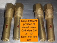
Screw settings recorded, I extracted all the screws careful to keep them sorted lest they have subtle differences. I don't think they do though. It was interesting to see that the screws were actually small assemblies comprised of the brass screw, spring, small washer/shim and a puny rubber O-ring. Sliding the O-ring off freed the shim and spring. I think the Litetek carb kit came with replacement rubber and shims. I'll have to dig them up.

The screw appear a little dull and tarnished but mostly clean. I sorted them into their numbered baggies and will eventually ultrasonically clean them in batches. Making progress :ride
 

Attachments

  • 4 Pilot mixture screw shim.jpg
    4 Pilot mixture screw shim.jpg
    56.7 KB · Views: 19
  • 3 Pilot mixture screw apart.jpg
    3 Pilot mixture screw apart.jpg
    61.6 KB · Views: 23
  • 2 Pilot mixture screw assembly.jpg
    2 Pilot mixture screw assembly.jpg
    62.5 KB · Views: 20
  • 1 Pilot mixture screw.jpg
    1 Pilot mixture screw.jpg
    96.9 KB · Views: 26
  • 0 Pilot mixture screw and phillips driver.jpg
    0 Pilot mixture screw and phillips driver.jpg
    226.7 KB · Views: 29
Assuming these carbs are typical design, the low speed circuit consists of air flowing through the slow air jet in the air filter end of the carb throat mixed with fuel metered through the slow jet. That mixture enters the carb throat, usually through two holes, one right at the closed throttle plate and one slightly downstream. One of those small holes is adjustable via the mixture screw, so CCW turning richens the mixture from idle up to about 1/8 throttle. The screws have virtually no effect at larger throttle openings, and like I say they only control a portion of the low speed circuit so you don't need to get too concerned about exact adjustment, they are only used to adjust for a smooth idle and good response as the throttle is cracked open.
 
Rick - Not to dissuade you from asking questions here, but a lot of these can be answered by searching on the 400greybike forum.
 
Last edited:
Rick - Not to dissuade you from asking questions here, but a lot of these can be answered by searching on the 400greaybike forum.

Yeah, I've done that but there is mostly NC30 discussion and I found a few NC35 discussions confusing or incomplete. Perhaps it's the Brit speak that throws me off. I'll dig more.
 
Here are some photos showing the variety of shapes for flat blade driver bits. Maybe there isn't a standard.

The driver bit that fills the slot is less likely to cam out or damage the screw.
Sloped faces apply force on small area :thumbdown.
Flat faces contact more area minimizing damage :thumbup

+1 to using that hollow ground screwdriver bit for this kind of work. Also sold as "gunsmith" screwdrivers.
 
:loco this tedious work makes my teeth chattery:teeth
 
Last edited:

Thanks. That's one of the threads. Please decipher: "its currently running a 3/4 yammy and is not on 112's all round with an extra .5mm washer.
it was running 115f 117 rear, and pulled like the clappers up top."

Yammy means what?

Clappers mean good or bad?

I reread the entire thread and having a better understanding of carb function, terminology, parts, etc. I get maybe 90% now. I'll refer back to it as I make more progress.
 
Assuming these carbs are typical design, the low speed circuit consists of air flowing through the slow air jet in the air filter end of the carb throat mixed with fuel metered through the slow jet. That mixture enters the carb throat, usually through two holes, one right at the closed throttle plate and one slightly downstream. One of those small holes is adjustable via the mixture screw, so CCW turning richens the mixture from idle up to about 1/8 throttle. The screws have virtually no effect at larger throttle openings, and like I say they only control a portion of the low speed circuit so you don't need to get too concerned about exact adjustment, they are only used to adjust for a smooth idle and good response as the throttle is cracked open.
Bill, thanks for the info packed posting. My understanding:
A carb's function is to mix fuel and air at the optimum ratio depending on RPM.
A carb's design can be broken into two circuits: low (idle-1/8 throttle) and high (1/8-wide open throttle).
These functions are mostly independent and can be considered/set separately. Mostly right?

Postings like the one Krooklyn linked talk about upgrading jets and needle shims are a bit too advanced for me just now.

Can someone explain why setting the float height is so critical? How does bowl fuel height make for lean or rich as the carbs are "just" sipping fuel from a puddle. I envision the fuel level bouncing way more than 1mm due to road and engine vibration. Can someone explain theory and reality?

+1 to using that hollow ground screwdriver bit for this kind of work. Also sold as "gunsmith" screwdrivers.
Must...resist...buying....more...tools....
 
Session 27: Float leak test

Tested floats for leaks last night. Used chopsticks (Japanese bike, duh!) and held them submerged in a glass jar filled with water (soy sauce was too dark). No bubbles formed and no water sound inside floats. :thumbup
 

Attachments

  • Carb float leak test 3.jpg
    Carb float leak test 3.jpg
    56 KB · Views: 31
  • Carb float leak test 2.jpg
    Carb float leak test 2.jpg
    69.6 KB · Views: 45
  • Carb float leak test .jpg
    Carb float leak test .jpg
    76.4 KB · Views: 36
Last edited:
Tested floats for leaks last night. Used chopsticks (Japanese bike, duh!) and held them submerged in a glass jar filled with water (soy sauce was too dark). No bubbles formed and no water sound inside floats. :thumbup
Water? You should have tested it on a jar of gasoline. :later
 
Bill, thanks for the info packed posting. My understanding:
A carb's function is to mix fuel and air at the optimum ratio depending on RPM.
A carb's design can be broken into two circuits: low (idle-1/8 throttle) and high (1/8-wide open throttle).
These functions are mostly independent and can be considered/set separately. Mostly right?

Postings like the one Krooklyn linked talk about upgrading jets and needle shims are a bit too advanced for me just now.

Can someone explain why setting the float height is so critical? How does bowl fuel height make for lean or rich as the carbs are "just" sipping fuel from a puddle. I envision the fuel level bouncing way more than 1mm due to road and engine vibration. Can someone explain theory and reality?

The float height changes the vertical distance the fuel needs to be raised by the vacuum in the intake. Therefore it influences the mixture. Adjusting the height can fine-tune the mixture if you have some subtle problem like a surge or sputter at certain throttle setting. Getting it "close enough" should be close enough for just making the bike run. You can fiddle with it later if you feel the need.

As you mention, sweating about the exact float height is ridiculous when you think about what happens to a moving motorcycle. All you really need is to submerge the end of the main jet under typical conditions, but don't submerge it so much that there's fuel pouring out of some hole in the carb.
 
Thanks. That's one of the threads. Please decipher: "its currently running a 3/4 yammy and is not on 112's all round with an extra .5mm washer.
it was running 115f 117 rear, and pulled like the clappers up top."

Yammy means what?

Clappers mean good or bad?

I reread the entire thread and having a better understanding of carb function, terminology, parts, etc. I get maybe 90% now. I'll refer back to it as I make more progress.

Yammy = Yamamoto 3/4 exhaust (almost a full system)

Clappers = fast - (https://www.phrases.org.uk/meanings/like-the-clappers.html)
 
Water? You should have tested it on a jar of gasoline. :later
No have gasoline in our kitchen. :x Sigh, back to the cave .

The float height changes the vertical distance the fuel needs to be raised by the vacuum in the intake. Therefore it influences the mixture.......but don't submerge it so much that there's fuel pouring out of some hole in the carb.
Thanks for this. Makes sense. It's just that I see a lot of posts about people being so exact for float heights. I will set mine accurately to spec to get a baseline.

Yammy = Yamamoto 3/4 exhaust (almost a full system)

Clappers = fast - (https://www.phrases.org.uk/meanings/like-the-clappers.html)

Cheers, mate! All I could think was he had some frankenstein Yamaha carb medley going on.

I can safely say my NC35 project progress is not going clappers.
 
Last edited:
Bill, thanks for the info packed posting. My understanding:
A carb's function is to mix fuel and air at the optimum ratio depending on RPM.
A carb's design can be broken into two circuits: low (idle-1/8 throttle) and high (1/8-wide open throttle).
These functions are mostly independent and can be considered/set separately. Mostly right?

Actually there is a continuum of throttle opening, rpm and air velocity through the carb, and the carb needs to maintain correct mixture in all conditions. For low throttle openings and low air flow thought the carb, the idle and slow speed circuit is in play - mainly the slow jet and idle mixture adjustment screw (and by the way that 400greybike forum post linked above is wrong, your mixture screw is CCW=richer, CW=leaner). As throttle opening and rpm increase, the throttle slide needle comes into play. The diaphragm lifts the throttle slide and needle automatically to maintain consistent vacuum in the carb venturi, hence the name CV "constant velocity" carb. At very low rpm and high load, slamming the throttle wide open will not lift the CV slide since rpm and therefore air velocity will not increase, so you will still be using mainly the slow circuit. But under normal acceleration, where opening the throttle leads to increased rpm and air velocity, the CV slide raises along with rpm and the tapered slide needle (jet needle) raises out of the needle jet and increases fuel flow into the carb throat from the main jet. At midrange running the slow speed circuit is contributing some mixture, but the main jet moderated by the jet needle and needle jet are still restricting full main jet flow. Only when the CV slide and its tapered needle are fully raised at 3/4 to full throttle and high rpm does the main jet totally dominate the mixture.

Can someone explain why setting the float height is so critical? How does bowl fuel height make for lean or rich as the carbs are "just" sipping fuel from a puddle. I envision the fuel level bouncing way more than 1mm due to road and engine vibration. Can someone explain theory and reality?

Float level is not really a variable used for adjusting mixture. It sets the correct level of fuel in the float bowl so all jets are adequately submerged but now so high that fuel overflows. Yeah float level affects mixture but it's not the right way to do it. Fine adjustment of mixture is done by idle mixture screw (for best idle), slow jet size (for <1/4 throttle), shimming needle height (~1/4 - 3/4 throttle), and main jet size (~1/2 - full throttle). Having the float level in the correct range allows the jets, which actually DO the metering of fuel, to do their job while actual float bowl level is sloshing around as you ride over bumps.

-Bill
 
...(and by the way that 400greybike forum post linked above is wrong, your mixture screw is CCW=richer, CW=leaner).....

Been spending many hours reading and studying interwebs all about carburetor theory, tuning, design, etc. Interesting and still mysterious. :loco

From what I gather, because my NC35's carb's mixture screw is on the engine side of the throttle plate (there are exceptions) I think Bill is correct: "CCW=richer, CW=leaner".

Another way to know is to look at the screw tip. If pointy it meters fuel. Mine are pointy.

For a physical check I inspected my carbs. There is a 2mm orifice on the downstream portion of the carb throat 10mm past the throttle plate. Peering inside the hole I can catch a glimpse of the side of the mixture screw moving back and forth as I turn the screw. Additional fuel must come thru here. What is a mystery is how the fuel is supplied to the mixture screw. Where does it flow from and what is its path? I can't see :( Maybe someday I can find the answer.

Bottom line, set the mixture screw to their last settings and then tweak them it once the engine runs.
 

Attachments

  • Mixture screw orifice 1.jpg
    Mixture screw orifice 1.jpg
    57.1 KB · Views: 31
  • Mixture screw orifice 2.jpg
    Mixture screw orifice 2.jpg
    84.7 KB · Views: 36
  • Mixture screw orifice 3 .jpg
    Mixture screw orifice 3 .jpg
    48.7 KB · Views: 33
Last edited:
Session 28: Jet cleaning

Having removed all brass bits from the carbs, I cleaned them of their varnish crud by submerging them in a cup of acetone for 10 minutes and then wiping them down with a clean cloth. They came out mostly clean but still tired and tarnished looking.

Since all my metal polishes were at the bat cave, I scrounged under the kitchen sink and pulled out a bottle of Weiman's Glass Cooktop Cleaner. What the heck, let's see what it can do!

I squirted a dab on an emulsion tube and worked it with the clean cloth. Like magic it removed the tarnish and made the brass sparkle :thumbup Take a look at the photos and you'll see what I mean. I used a brush to get into the small holes.

Looking up the ingredients the Weiman's contains water, pumice, alcohol and silicone. Lesson for the day: glass cooktop cleaner is an excellent brass cleaner :laughing

p.s. the RVF400 carbs have two types of emulsion tubes. Note the spacing of the triplet of holes. Cylinders 2&4 (toward the front of the bike) have uneven spacing whereas rearward cylinders 1&3 are more evenly spaced.

Here's what I read "The rears get warmer due to less air flow so are run slightly richer than the front (hence the hole differences)". http://www.400greybike.com/forum/viewtopic.php?f=24&t=12131
That make sense to anyone?
 

Attachments

  • 2 Dirty carb brass.jpg
    2 Dirty carb brass.jpg
    108.4 KB · Views: 45
  • 3 Impromptu metal cleaner.jpg
    3 Impromptu metal cleaner.jpg
    60.9 KB · Views: 32
  • 4 Cleaning carb brass 7.jpg
    4 Cleaning carb brass 7.jpg
    75.6 KB · Views: 30
  • 6 Clean carb brass 1.jpg
    6 Clean carb brass 1.jpg
    102.5 KB · Views: 37
  • 7 Jet holder aka emulsion tubes.jpg
    7 Jet holder aka emulsion tubes.jpg
    115 KB · Views: 32
  • Screen Shot 2018-03-08 at 1.01.02 AM.jpg
    Screen Shot 2018-03-08 at 1.01.02 AM.jpg
    74.4 KB · Views: 44
Last edited:
Back
Top